Texture Synthesis and Transfer
roger.lol / Texture Synthesis and Transfer
Roger Ngo, urbanspr1nter@gmail.com
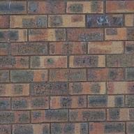
Random Sampling
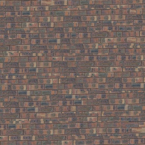
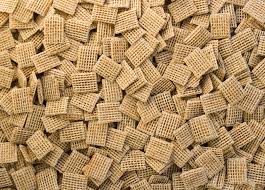
In this approach I have synthesized a larger image using a regular texture by sampling random patches of \(51x51\) pixels within the texture and tiled them programmatically onto the destination image.
Example
-
out_size = 500 -
patch_size = 51
By looking carefully, you will be able to observe that the output image was synthesized by laying out random patches due to the regular edges created in-between patches.

Minimal SSD and Overlap Sampling
This is a major improvement over the random sampling approach. The
method involves tiling the patches sampled from the input texture
in an overlapping manner. An overlap parameter
defines the region of the number of pixels which will overlap the
previous patch \(T_{prev}\) in both the top (horizontal), and left
(vertical) directions. This means that the current patch
\(T_{curr}\) being processed will overwrite a portion of
\(T_{prev}\) in the image.
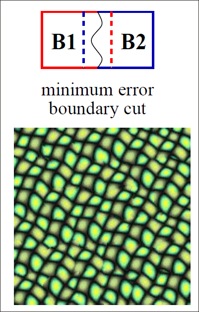
Here is an example taken from the original paper in how a sample
block is chosen, and tiled against the previous sampled block
within an overlap number of pixels.
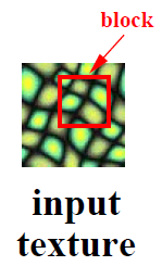
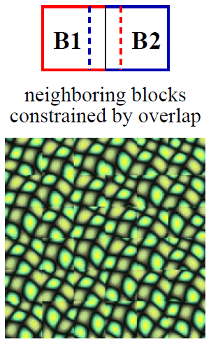
A block from the input sample texture \(I\) is determined through finding the pixel with the minimal sum of squared differences (SSD) value. For each block within \(I\) needing to be chosen, we use the current block from the destination image \(T_{curr}\), which already has some pixel information from the overlap pixels of the previous block \(T_{prev}\).
Using block \(T_{curr}\), a mask is created to only contain pixels which occupy the overlap region in both \(T_{curr}\) and a current block within \(I\). We then use the region of pixels in both blocks with the mask applied to find the SSD of this overlap region through the use of linear filters. We do this calculation against all pixels within the input sample \(I\). The minimal value is chosen to be the center pixel of the chosen sample patch of the input texture.
We can also vary the types of patches chosen and instead of
choosing the minimal cost each time, and leverage a
tol parameter to randomly select a cost in the number
of tol
values.
This process is repeated for the entire image.
Example
-
out_size = 500 -
patch_size = 51 -
overlap = 25 -
tol = 10
Synthesized with patches with minimal SSD value and
overlap
(out_size = 500, patch_size = 51, overlap = 25, tol = 10)
Minimal SSD, and Overlap with Seam Finding
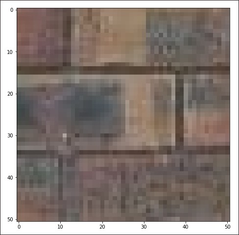
This is an improved version of the previous approach. Like the previous algorithm the approach is to tile the patches through an overlap region, except there is now an additional step in that we want to be able to overlap in such a way where the final result looks seamless.
We first take the image patch \(T_{curr}\) which has been partially filled through overlapping it with the image patch \(T_{prev}\) constructed from the previous iteration.
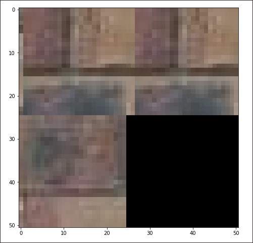
Then we will find the SSD of all pixels in the sample image \(I\) using the overlap region (the partially filled portion of the image patch) as the source. Similar to the previous approach with just minimal SSD and overlap, we mask this region to obtain the cost values by the use of filtering.
The result is a grid of cost values representing the cost of selecting each pixel at the sample texture. The pixel selected is considered to be the "center pixel" of the sample patch chosen.
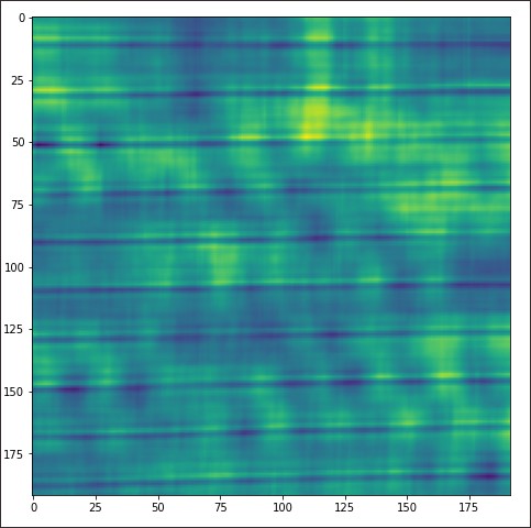
By finding the minimal cost within the SSD cost image, we can use it as a center pixel and expand across to get the coordinates of the sample patch.
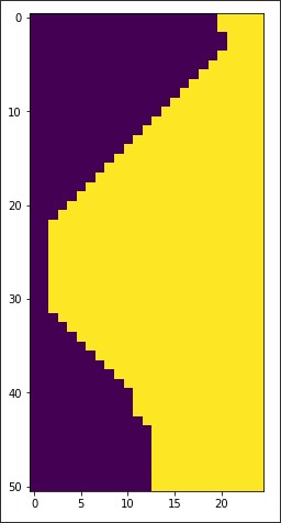
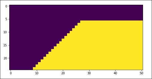
Once we have found a matching block from the input sample texture, we will choose to actually use only parts of the overlap region in both the block that has been sampled and the region from the block that is being overlapped by in the top and left directions.
To do this, a seam with minimal error is found within the top and left overlaps. This seam dictates that if removed, the overlap regions from both blocks will transition in a smooth manner.
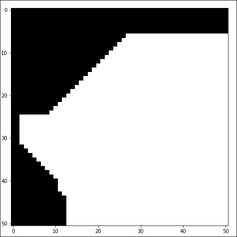
We do this in both the top (vertical) and left (horizontal) overlap regions by creation of mask images. After obtaining these masks, we combine them to create a mask which determines which pixel we should use for the image patch, and which should be used from the sample patch.
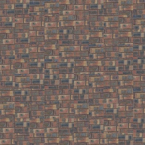
The following below shows the output with the brick texture.
Example
-
out_size = 500 -
patch_size = 51 -
overlap = 25 -
tol = 10

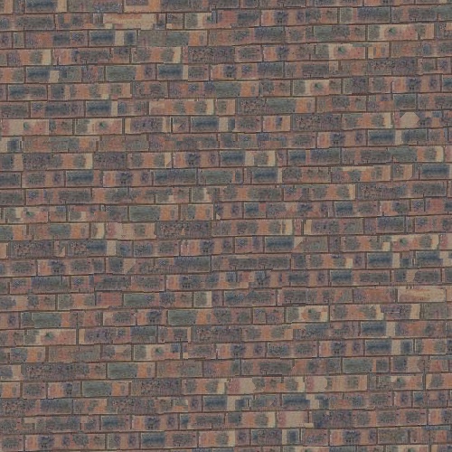
(out_size = 500, patch_size= 51, overlap = 25, tol =10)
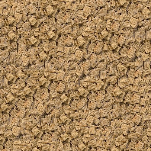
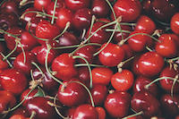
Additional Texture Synthesis Using Seam Finding Results
Here are additional results:
Parameters:
-
out_size = 500 -
patch_size = 51 -
overlap = 25 -
tol = 10
Parameters:
-
out_size = 500 -
patch_size = 51 -
overlap = 25 -
tol = 3
Parameters:
-
out_size = 500 -
patch_size = 31 -
overlap = 15 -
tol = 5
Texture Transfer
The texture transfer algorithm which was implemented was the same algorithm described in the Efros and Freeman paper. The general approach can be seen as texture synthesis combined with choosing image patches with a constraint in matching patches from a guidance image based on some weighted cost.
Instead of the SSD calculation performed in texture synthesis, SSD is now composed of the two previous described terms:
$$SSD = \alpha SSD_{overlap} + (1 - \alpha) SSD_{guidance}$$
Note that the greater the \(\alpha\) value, the more the calculations will steer towards choosing a patch that is similar to texture synthesis. The smaller the \(\alpha\) the more the cost will steer towards the guidance image.
To calculate the \(SSD_{overlap}\), we use the input texture, and image patch to be filled.
To calculate the \(SSD_{guidance}\), we need to first create a correspondence map of the input texture, and the guidance image. The paper descibes as taking the intensity values of these images, and applying a Gaussian blur to them. We use these as inputs to compute the SSD between the input texture and guidance.
There are a few caveats to texture transfer. One must take into consideration that:
- The very first patch placed in the image at (0, 0) must be the patch with the minimal SSD value. That is, we select the patch from the input texture where \(SSD_{overlap} = 0\).
-
Unlike texture synthesis, with texture transfer, we always
select the minimal value to sample within the texture image.
That is equivalently, in synthesis terms,
tol = 1. - Smaller block size and larger proportion of overlap will lead to finer results. This is the basis for iterative texture transfer.
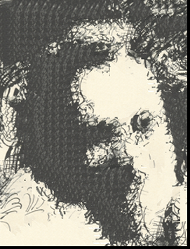
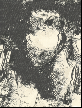
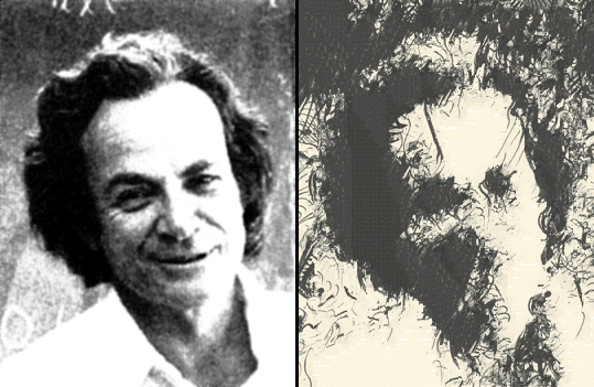
Sketch + Feynman
-
patch_size = 9 -
overlap = 3 -
tol = 1 -
alpha = 0.1
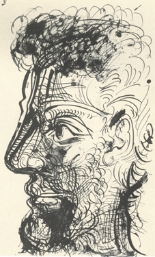
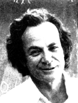
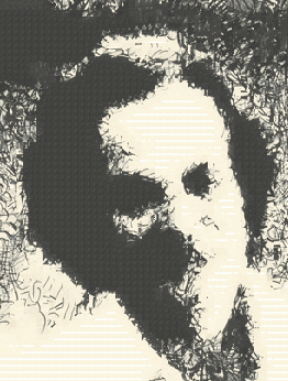
(patch_size = 9, overlap = 3, tol = 1, alpha = 0.1)
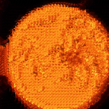
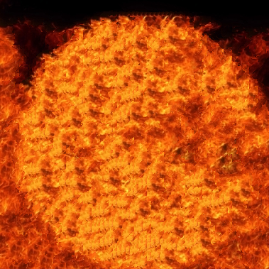
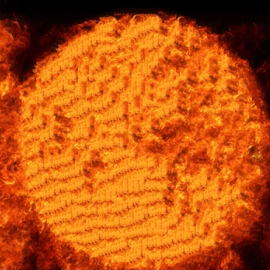
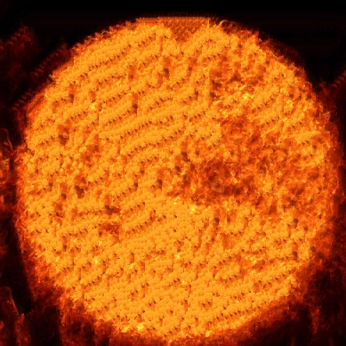
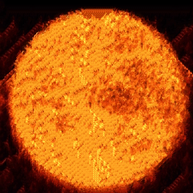
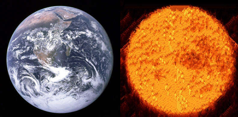
Fire + Earth
-
patch_size = 9 -
overlap = 3 -
tol = 1 -
alpha = 0.1
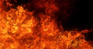
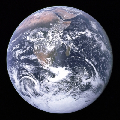
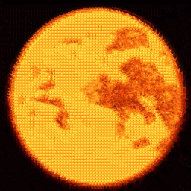
(patch_size = 9, overlap = 3, tol = 1, alpha = 0.1)
Painting + Riley
-
patch_size = 9 -
overlap = 3 -
tol = 1 -
alpha = 0.1
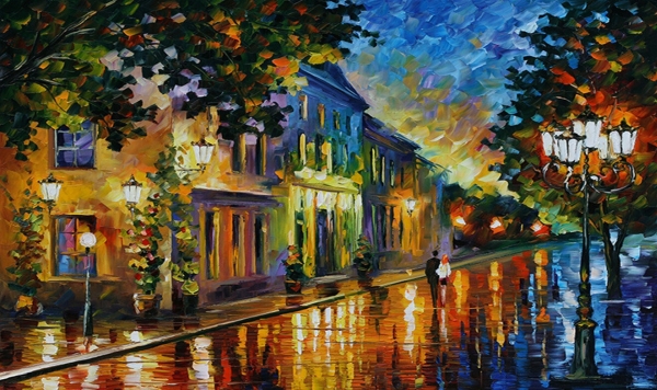

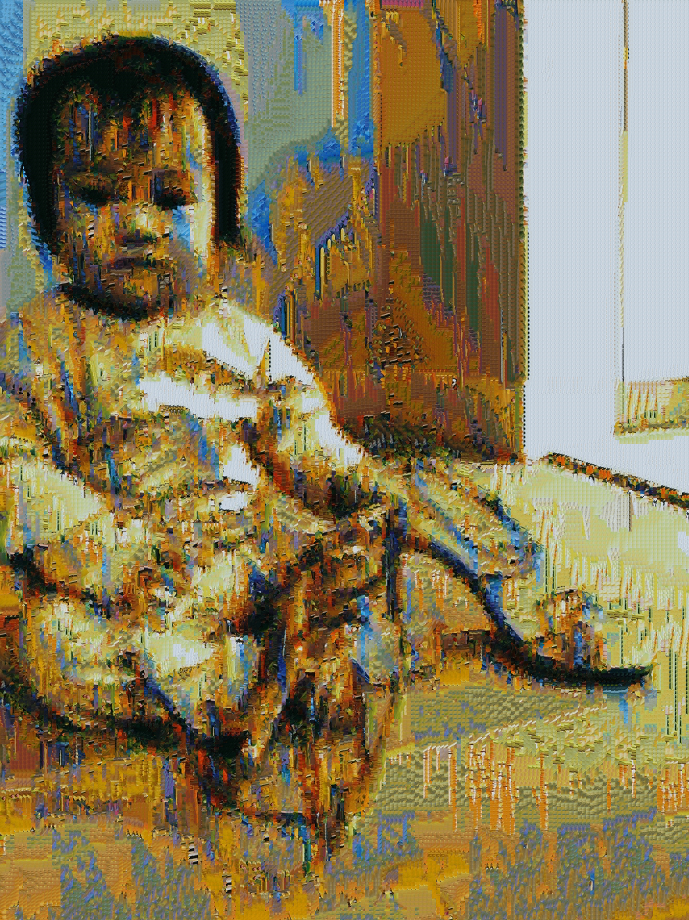
(patch_size = 9, overlap = 3, tol = 1, alpha = 0.1)
Bells and Whistles
Iterative Texture Transfer
The method for iterative texture transfer is similar to a single iteration of texture transfer, except that we introduce a third term into the calculation for the SSD.
Instead of simply computing \(SSD_{overlap}\) with just the input texture and image patch, we must also sum up the previous SSD image in computation.
Therefore, the algorithm must remember the SSD for the particular pixel falling into a patch from the previous iteration. We use this to augment the cost value of the overlap to give more influence in values selected before.
Thus computing the SSD becomes:
$$SSD = \alpha(SSD_{overlap} + SSD_{prev}) + (1 - \alpha)SSD_{guidance}$$
For each iteration \(i\) of \(N\), we must modify the following:
- patch_size
- overlap
- alpha
For each iteration, the patch_size and
overlap are reduced by \(\frac{1}{3}\) each time. By
default we start with patch size \(31 \times 31\) with an overlap
region of \(21\) pixels.
The \(\alpha\) value is initially \(0.1\) and is altered with the following expression at each iteration:
$$\alpha_{new} = 0.8 * \frac{i - 1}{N - 1} + 0.1$$
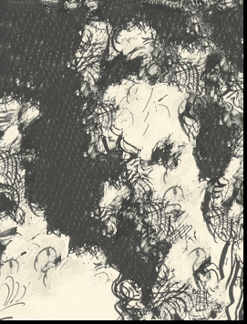
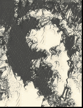
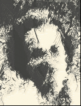
As the number of iteration increases, the less blocky the result seems to be, and fidelity in parts of image increases.
For the iterative version of the Sketch + Feynman example, we see that by \(N = 5\), the output image looks like a sketch. The initial parameters were:
-
patch_size = 31 -
overlap = 21 -
tol = 1 -
alpha = 0.1 -
N = 5
For my method the smallest granular patch and overlap size was \(9\) and \(3\) respectively.
For this next example, the same parameters were used as with the previous iterative texture transfer.
-
patch_size = 31 -
overlap = 21 -
tol = 1 -
alpha = 0.1 -
N = 5
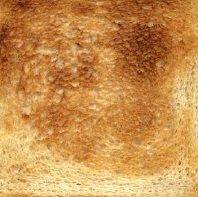
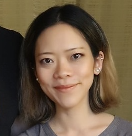
Face in Toast
To build a "face in toast" image as seen in internet urban legends, it is a multi-step process.
- We choose a texture that resembles that of toast.
- Select the guidance image (the face)
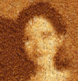
- Apply texture transfer on the images from (1) and (2)
- Save this result
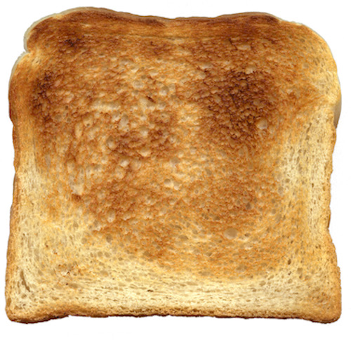
- Select an image of toast (the image for which the face should appear on)
- Apply Laplacian blending on (5) and (6)
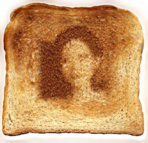
Laplacian blending involves constructing the Laplacian pyramids for both the face and toast image. Before combination, we create a mask which dictates where the face will be placed in the toast image. We then use the mask to create a Gaussian pyramid.
Using the Gaussian pyramid of masks, we perform multiplication on the images at each level of their respective Laplacian pyramids and collapse into a single image. This creates the effect of "face in toast".
Credits and Attribution
Aside from sample images provided, I used my own personal images of myself and family. The other images come from:Texture Synthesis
- Cereal texture - https://pxhere.com/en/photo/1160137
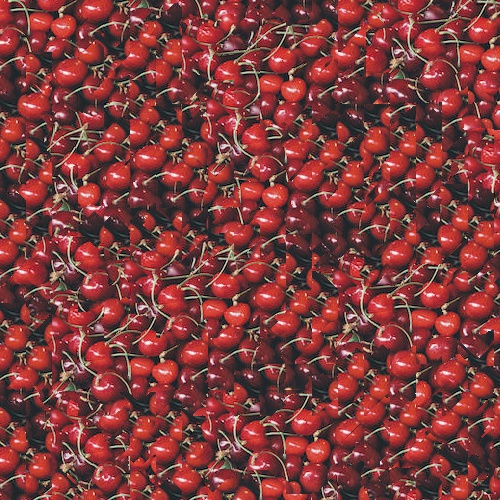
- Cherries texture - https://www.deviantart.com/8moments/art/texture-cherries-651737153
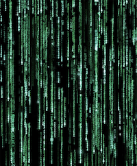
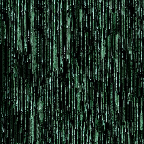
- Matrix code texture - https://matrix.fandom.com/wiki/Matrix_code
Texture Transfer
- Painting is "On the Way to Morning" by Leonid Afremov
- Earth - Wikipedia article on Earth
- Fire - https://www.wdbj7.com/
Last modified: February 2021, Roger Ngo, urbanspr1nter@gmail.com